Final version Appeared In Gas Engine Magazine Oct/Nov 2020
Introduction
The purpose of this article is to bring some understanding in a nontechnical way as to how the simple battery and coil and the low-tension rotary magneto ignition systems work. Expressions like “the coil kicks back” add no intuitive understanding and certainly don’t help us troubleshoot a nonrunning engine. In addition to a nontechnical understanding I hope I can clarify false statements and claims heard about low tension ignition systems. There are only 2 equations in the article, neither need to be used.
Section 1 Battery and Coil – Get Your Current Up
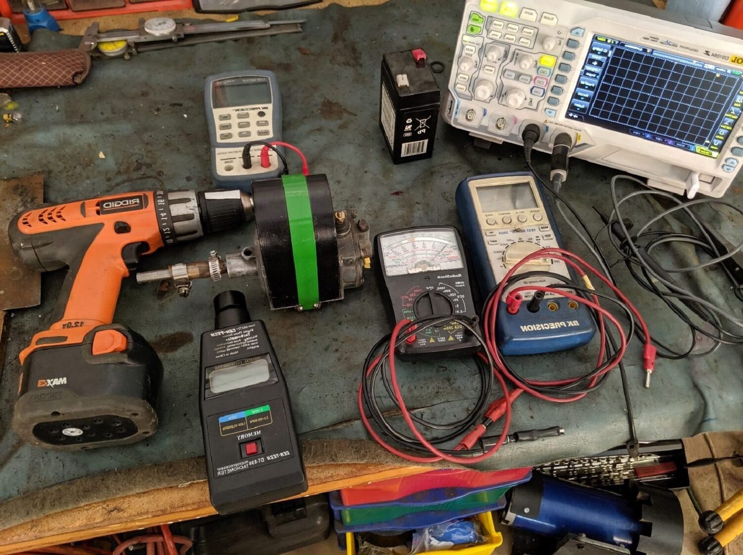
It’s best to begin with the simple coil and battery system then progress to the rotary magneto and igniter system. As seen in Figure 1-1 the equipment used to gather all the data was not exotic: Radio Shack analog multi meter, BK digital multimeter, Harbor Freight frequency meter, variable speed electric drill, rubber hose connector, 6V battery and two less common items, an LCR meter and an oscilloscope. The only tools you would need to analyze either system are a multimeter and a variable speed drill to spin a magneto.
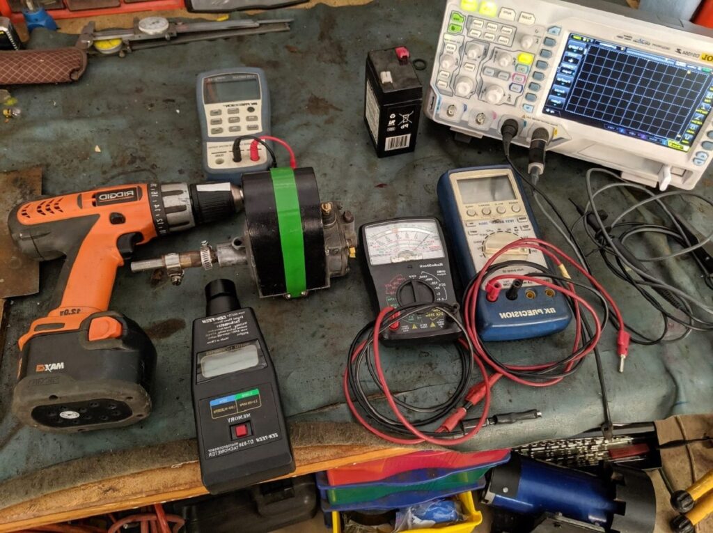
Figure 1-1 – The Work Bench
In Figure 1-2A I have taken the coil, battery and igniter off an engine and placed them on the work bench to make taking data a bit easier. The coil, which I call Fancy Coil, is one of those good-looking coils sold at swap meets, typically wound on a 1” steel rod about 3” to 6” long with 3” hardwood ends and two knurled brass thumb nuts to contact the pretty copper wire. The battery is a standard 6V Home Depot item that will run an engine through a two day show without a recharge. The igniter is off a 4 HP Waterloo Boy. The connection is typical of what is often used, but not the only correct way to connect the three elements. The red wire is from battery positive ( + ) to one terminal of the coil, the green wire is from the other terminal of the coil to the isolated igniter terminal, the black wire, typically called ground, goes from the igniter base/engine block to battery negative ( – ). Figure 1-2B schematically shows the circuit: a battery (V), a coil (L) with its internal resistance (R) and an igniter switch (S). Coils are labeled L in the electronics world, named after Emil Lentz, an early 1800’s physicist. The igniter switch is designed to snap open very quickly when it’s called on to react. As an aside, in the electronics world coils are called inductors just as condensers are called capacitors.
The following data was taken using a different but very similar coil that I will call Fancy Coil2. Other coils may be shaped differently, have a different number of turns but will behave in a very similar manner.
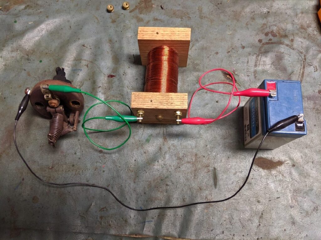
Figure 1-2A Typical battery, coil and igniter connection.
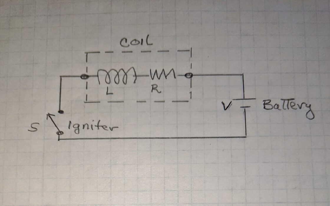
Figure 1-2B. Connection Schematic
As strange as it may sound, a look at a flywheel will shed some light on how coils behave. It is impossible to take a sitting flywheel to 500 RPM instantly. Rather, apply a lot of effort over a period of time and it will accelerate upward from zero. Once rotating at 500RPM it has a huge amount of stored energy. That stored energy is proportional to (RPM)2 and mass distribution (further from the center the better). Because RPM is squared, doubling the RPM increases the stored energy by a factor of 4. Once the applied force is stopped the flywheel will begin to slow down as it dissipates its stored energy. With no external load the dissipated energy is converted to heat energy in the bearings, cylinder and other moving areas. Conservation of energy does not allow energy to evaporate, it can move or change form but not just disappear. In fact, the flywheel will not stop turning until it has dissipated all of its stored energy. There is a force and time relationship here. Apply a small force over a long period of time, resulting in a lot of stored energy. In a like manner, as the fly wheel slowly winds down it is hardly noticeable that the bearings, etc. get warmer but try to slow it down quickly by grasping the fly wheel and squeezing hard, those hands will get real hot, real fast. So, in general when you apply a load, the heavier the load, the quicker it dissipates its energy and the quicker it stops and the more concentrated the heat. But here is an important point: it is impossible to instantly stop a big heavy rapidly spinning flywheel. The rotating energy must be transferred to some other place (heat or other moving parts) and that process takes time. Rather than the term stored energy, it might be said that the flywheel has a lot of momentum or inertia. It’s hard to get it rolling but once rolling it’s difficult to stop.
Unlike the flywheel if you apply a voltage (force) to a resistor, the current, I (Amps), will instantly jump to its final value of the voltage (V) divided by the resistance (R). Ohm’s law says I=V/R. That’s the first equation. An inductor (coil) is not like the resistor but is very similar to the flywheel. When voltage is applied to a coil (similar to the force on a flywheel) the current does not immediately jump to its final value. Rather it starts at zero and ramps up toward its final value just like the flywheel starts at zero RPM and ramps up. The coil current ramp rate is a very well-defined exponential based on physical properties. The final value, once it gets there, will be the voltage divided by the coil resistance, V/R. But, again, it takes time for it to get to the final value. Figure 1-3 schematically demonstrates how to measure the current rise time of a coil, in this case, Fancy Coil2. In that schematic the I symbol represents the oscilloscope being used as a current meter. Figure 1-4 shows that it took about 200 ms (0.200 s) for the current to reach close to its final value of 0.8 A.
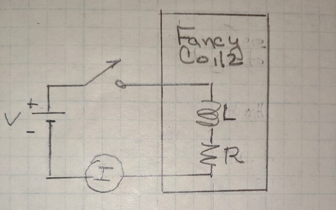
Figure 1-3 – Measuring current rise time of an inductor/coil
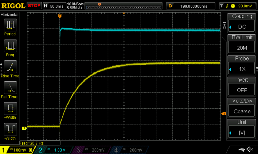
Figure 1-4 – Current rise Time of Fancy Coil2. Yellow Vertical Scale 0.2A/box, Blue Vertical Scale 1V/Box, Horizontal 50ms/Box (0.050S/box).
For those not familiar with oscilloscope pictures, think of them as the paper plotters seen on TV for lie detectors or during earthquakes. The paper moves along while the needles move in response to inputs such as heart rate or ground shakes. The paper might move a few inches a day or a few feet per minute. Looking at a section of the paper after the test, time is progressing from left to right while vertical movement is measuring an input. The oscilloscope picture in Figure 1-4 is a section of the paper plot but now the paper is moving 1000s of feet per second while the vertical movement will be a measure of voltage or current. At a 1000 feet per second one foot of the plot has recorded 1/1000 or 1ms of time.
Here in Figure 1-4 the time scale left to right is 0.050 Second ( 50ms) per box. At about 100ms from the left 6 Volts was applied to the coil (blue trace). At that point the current begins to rise with the yellow vertical scale being 0.2A per box. From application of the 6V, 1 box (50ms) later the current has risen a little over 2 boxes (0.4A). Finally, after about 4 boxes of time (200ms) the current has risen about 4 boxes (0.8A).
Taking about 200ms for the current to reach close to its final value may seem very fast, almost instantaneous, but this is electricity not flywheels. A modern cell phone could do about 400 million operations during that same time period. In fact, in the electrical world 200ms is very very slow. Why is the current rise time so important? Basically, it’s important to understand that coils don’t react instantly, sometimes you will need to wait around while the current ramps up. For example, the rise time tells how early the igniter points must close to allow enough time for the coil current to build up before the igniter trips. More on that a bit later.
Like the flywheel that stores energy as its RPM ramp up, when the current is ramping up, the coil is storing energy in the magnetic field that is building up around it. This stored energy can’t be seen or felt but it is real, as real as the spinning flywheel. The amount of stored energy is 1/2 LI2 where I is the current in amps and L the coil’s inductance in Henrys.
E= ½ LI2 is the second equation. It should be noted here that current is a big deal as this energy is the energy and thus the hotness of your spark and depends on current squared.
The inductance, L, (Henrys) is made up of many physical and geometric parameters such as the core dimensions (length, diameter) and material (iron, air), the number of wire turns, the wire gauge, etc. Once wound the coils inductance won’t change as it’s made up of those geometric and physical terms. Like the flywheel’s rapid increase in energy with RPM, the inductor or coil’s stored energy increases as the square of current. So, if the current in a coil is raised 2X the stored energy will go up 4X. Also like the flywheel that won’t stop spinning until all its stored energy is dissipated, if the voltage is disconnected on the coil the current in the coil won’t stop flowing until all the stored energy is dissipated. That’s an important point. A lot may get in its way, like opening the igniter points, but the current will continue to flow until all the coils energy is dissipated.
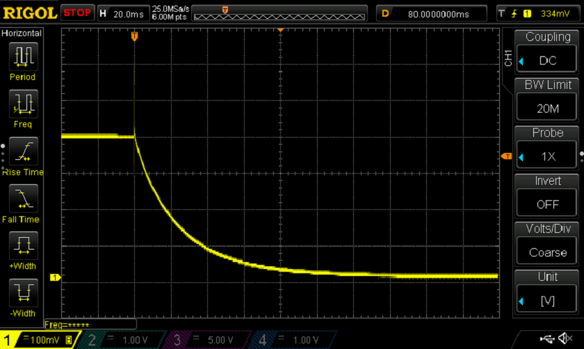
Figure 1-5 – Fancy Coil2 Dissipating Its Stored Energy through 17 ohm. Horizontal Scale 20ms/Box, Vertical Scale 0.2A/Box
In Figure 1-5, the 6V battery that has been connected to the coil is abruptly disconnected at 40ms after time started at the left. After the 6V is disconnected the current continues to flow but rapidly decreases in value as the stored energy is dissipated through 17 ohms of resistance, 10 ohms that were placed in the circuit and 7 ohms that are internal to the coil. Here the stored energy is converted to heat resulting in the resistors getting warmer. In the case of the flywheel the more load put on it the quicker it will stop. Here the higher the resistance the quicker the energy is dissipated and the sooner the current will stop flowing. With only a 17 Ohm load it takes well over 100ms for the coil to dissipate its stored energy and thus the current go to zero. Figure 1-6 is the reaction of Fancy Coil2 dumping its energy through 87 ohms. With the increased load the energy/current reach near zero in only about 40ms.
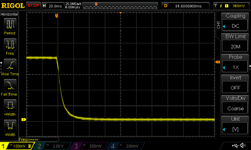
Figure 1-6 Fancy Coil2 dissipating energy through 80 ohms, horizontal scale 20ms per box
As with the fly wheel, there is an energy and time factor. Increase the load that a coil must dump its energy through, the time needed gets shorter and the heat becomes more concentrated. It might be suspected then that the igniter points popping open gives the coil a big load to dump its energy through resulting in a short hot spark.
Why is this important? The energy in the coil becomes the energy of the spark, that is, the hotness of a spark is exactly the stored coil energy. Want a hot spark, then store a lot of energy in the coil. Further that stored energy is proportional to current squared and it takes time to get current.
With the points closed and current flowing the coil has packed away 1/2L I2 energy in its magnetic field. When the points pop open it is expected that the current, I, will be zero and therefore the energy to be zero. The coil responds by saying OK I can do that but first give me some time and a way to get rid of all this energy. When the points pop open the current must continue to flow and dissipate the coil’s energy. It has no option but to jump/arc across the igniter points gap, dissipating massive heat until all the energy is dissipated and the current has ramped down to zero. The points popping open is very similar to shoving a crowbar into the spokes of a big 500 RPM flywheel: there will be some serious damage. How does the coil react to its crowbar? When the points pop open, the magnetic field begins to collapse around the coil resulting in a magnetic field moving across wires, this is generator action. The coil turns into a massive generator driving current across the igniter gap as it dissipates all its energy as heat in the arc. The term “coil kickback” is used here which is really the process of the coil moving its stored energy someplace else, the spark and heat.
We have some take away points here. First, the battery is an insignificant contributor to the spark voltage when the igniter trips. The battery function is to merely get the current rolling in the coil before the igniter trips. Second, the coil current is slow to rise because it is busily converting current, voltage and time into energy and storing that energy in its magnetic field. Third, when the igniter points pop open the stored energy is converted to heat in the gap as an arc. Fourth, the energy in the coil goes up as current squared, so get the current up. Fifth, the amount of energy stored in the coil is how hot the spark is, period.
You may have been given instructions on the correct way to connect a battery and coil to the igniter. If you prefer your electrons to flow left to right across the igniter points as opposed to right to left then there is indeed a correct way to make the connection. Recently the same engine was run in the four configurations of Figure 1-7. In the first two configurations the coil is between the igniter fixed point (nongrounded side/ terminal) and the battery, A and B reverse the battery (electrons left to right or right to left). In the second two configurations the coil is in the ground leg of the circuit, C and D reverse the battery. All four configurations ran the engine very smoothly. Personally, I prefer A (and is likely the one you’ve been told is correct) but it is a simple series circuit and the order of the component makes no difference.
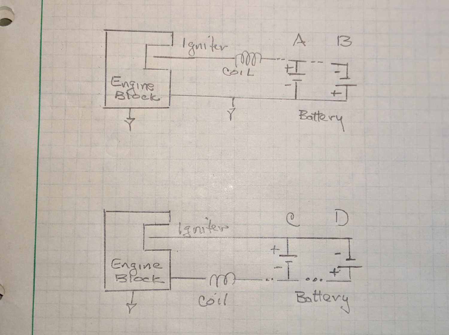
Figure 1-7 Multiple ways to connect the battery and coil
In the 1920’s, engine manufacturers, in order to gain the highest reliability over an expected 20,000 operating hours, very well may have defined one of the above as the proper configuration for their engine. But in the 20 hours you might run that engine in your lifetime, any of the four will work fine.
The flywheel and the coil were compared earlier, stooping a little lower to a toilet, might provide more insight. The toilet has the three things we need; energy source (inlet water), storage (the tank), time and a way to quickly release the storage tank (flush). The water inlet is too weak to flush the toilet by itself as it would just raise the water level in the bowl a bit, until equilibrium was reached with water flowing out at the same rate it’s coming in. That happens when a toilet has a bad valve and runs all the time. In a similar manner the battery alone is not sufficient to cause a good spark. Given time however the water inlet can store a large amount of water in the tank. The water can be seen rising with time. In a similar manner, given time the battery can store energy in the coil. Using an oscilloscope, the current can be seen rising, Figure 1-4. Once stored, turn the flush handle and very rapidly the stored water is released. The sudden release starts a chain reaction of rising water and siphon action. When the igniter points pop open, there is a sudden release of the coils stored energy. This sudden release of energy starts a chain reaction; arc, ionization of the gas and heat. Having flushed the toilet and tripped the igniter they both start the refill process. But this time don’t wait the full time to flush and trip, maybe the toilet tank is only a third full and the coil current is only up to 0.3A (Figure 1-4). Not enough water is dumped to get flush action and not enough coil energy is dumped to ignite the gas. So, how long does the wait need to be? The answer to that is important for battery life as well as a smooth-running engine. Battery and coil engines leave the igniter points open until around 60 or 70 degrees of crankshaft rotation before top dead center on the compression stroke. At that time the igniter points close and stay closed until the igniter trips and they pop open. This short time the points are closed before the trip keep the battery “on” time low. That short time that the points are closed is, however, hopefully enough time for the coil current to ramp at least part way up thus creating the necessary stored energy, see Figure 1-4. In a 1949 Chevy, the short time the points (igniter) are closed before opening to cause a spark would have been called the dwell time or dwell angle. At 400 RPM for the 60 degrees engines (igniter closes 60 degrees before top dead center), the points are closed for about 12ms to 16ms, depending on when the igniter is timed to trip, with the battery being used less than 5% of the run time.
Remember from Figure 1-4 and the toilet discussion, nothing happens instantly in a coil, apply a voltage and wait for the current to ramp up. So, let’s take a closer look at what is going on with a battery and coil engine with the igniter points being closed for such a short time before popping open again at trip. We have already shown that a 60 degree engine running at 400RPM will have the igniter points closed 12 to 16ms of dwell before igniter trip. In Figure 1-8, the time scale is expanded to see that Fancy Coil2 will ramp to about 0.2A each cycle and thus be storing 0.2A of energy to be dumped into the arc at trip. In the 1910’s the common size 6 battery was not rechargeable, shortening the battery on time would save battery power. If the points closing is moved to 30 degrees BTDC, they are now closed for around 4ms before the igniter trips and Fancy Coil2 will ramp to only about 0.05A. Its unlikely the engine will have any spark and probably won’t run, better go back to 60 degrees. Now a young person can crank that same engine at say 50RPM, the points will be closed for about 50ms and Fancy Coil2 will ramp to 0.45A each cycle. When cranking the engine, the coil has more than twice the current at trip that it does running. The hotness of spark which is stored coil energy goes as current squared. There is greater than 4 times more spark when starting the engine, that’s pretty handy.
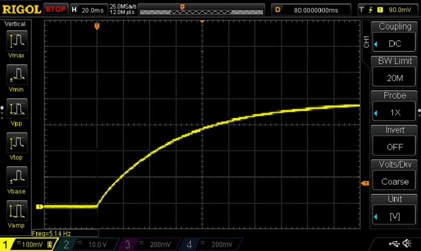
Figure 1-8 Fancy Coil2 current rise time expanded time scale. Horizontal scale 20ms per box. Vertical scale 0.2A per box.
Section 2 Low Tension Rotary Magneto
A low-tension rotary magneto, sometimes shortened here to mag, consists of three major components: a long fine wire (often 250 feet long, often 24 or 22 gauge), a way to contact to the ends of the wire and a magnetic field. Mechanically, the long wire is tightly wound (often 800 turns) in the shape of a coil to form an electrical inductor and placed in the magnetic field on an armature. The armature is shaped to focus the magnetic field through the coil. Operationally, the coil is rotated in the magnetic field. When a wire is placed in a magnetic field, as done here, a couple of interesting things can happen. If the wire is moved, a positive voltage will develop on one end or the other of the wire. The direction of voltage is dependent on the direction of motion. Yes, it’s a generator. On the other hand, if current is pushed into the wire, the wire will move as a motor. Search YouTube for “Let’s Build A Hit and Miss Engine Dyno” by Dr. David Cave to see a very nice demonstration of both phenomena (at about 9 minutes into the video).
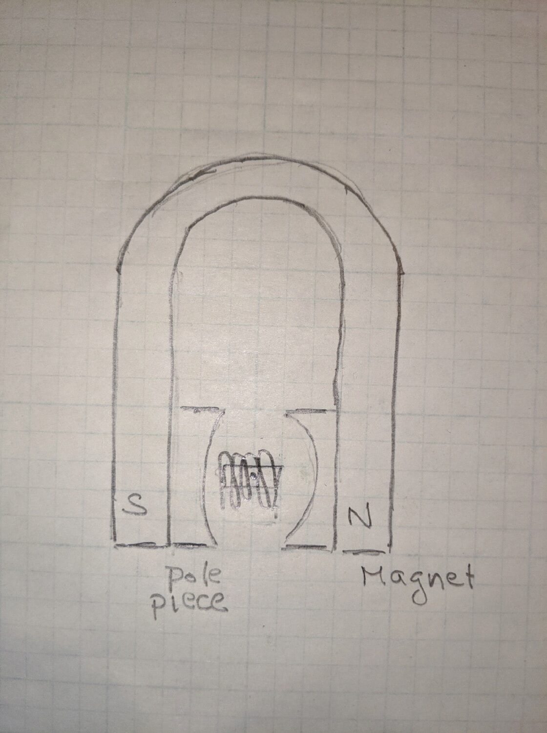
Figure 2-1A Simplified magneto cross section.
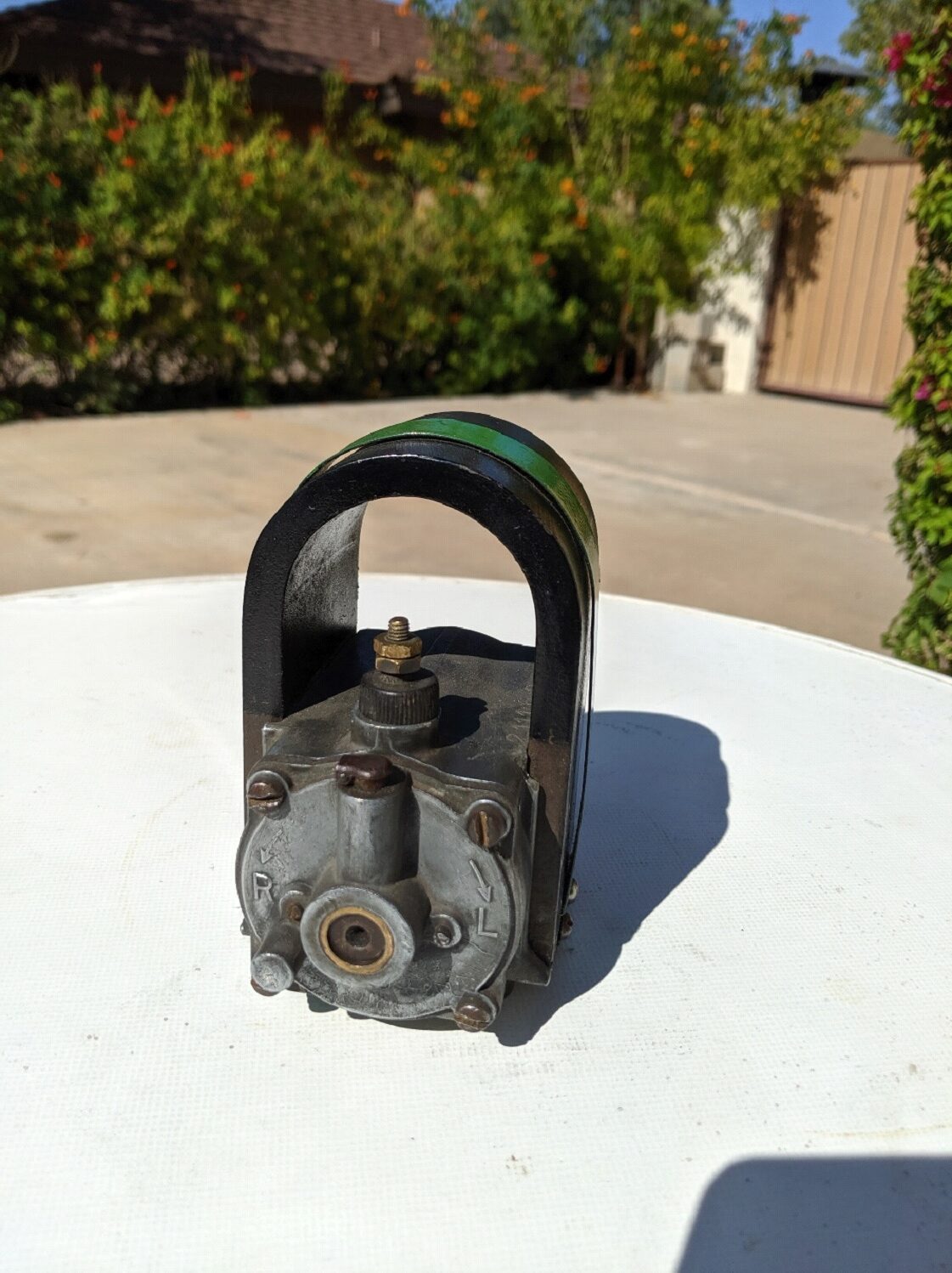
Figure 2-1B John Deere magneto
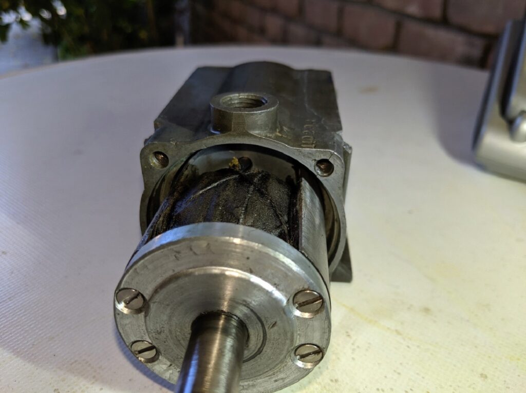
Figure 2-1C Armature partially removed
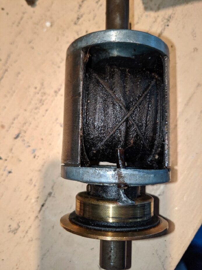
Figure 2-1D John Deere magneto armature, coil is visible
In the first part of this article, three circuit elements were used to create a spark: battery, coil and igniter. In the low-tension rotary magneto, the rotating coil performs two of those functions, the battery and the coil. Figure 2-2 shows schematically the magneto and igniter; an internal generator creating a voltage, the coil, L, and its internal resistance, R, connected to the igniter. Moving the coil in the magnetic field causes it to become a generator which causes current to build up inside itself when the igniter points are closed. That current inside itself then creates the magnetic field around itself which stores the energy for the spark as discussed in Section 1. So basically, the rotary low-tension magneto is just a mechanized battery and coil system where moving the coil replaces the battery. All those things discussed in Section 1 will still be true: the energy stored in the coil becomes the energy of the spark, the energy increases as I2 (get your current up) and the current takes time to go from zero to its final value.
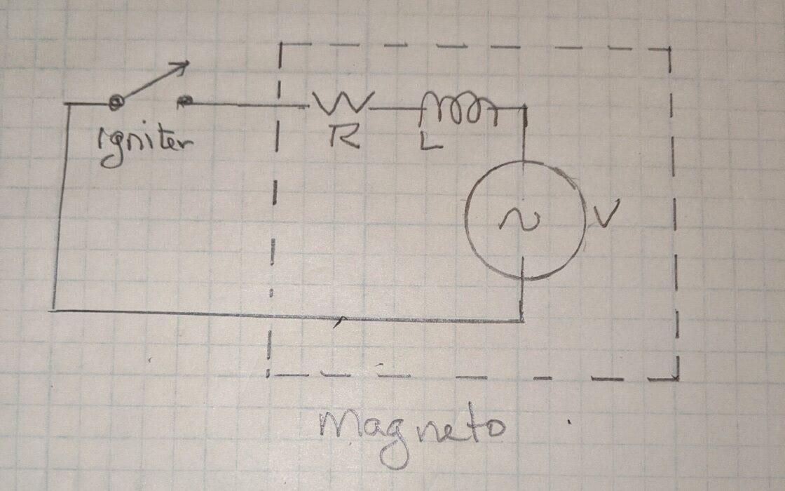
Figure 2-2
The John Deere magneto shown in Figure 2-1B was used to take data for the following discussion. Most low-tension magnetos have magnets and coils similar to those on the John Deere magneto and show similar characteristics. To show that the magneto coil behaves like a standalone coil discussed earlier, the armature was pulled out and measured. It was found to have a resistance of 5Ω and an inductance of 72mH. Figure 2-3 shows the rise time of current when 6 V is applied to the magneto coil. After application of the 6V the general shape of the response is very similar to Fancy Coil2’s response seen in Figure 1-4. The magneto coil rises faster, 60 to 70ms, and to a higher current but the general shape is the same. Those differences are because the magneto coil physical parameters differ: number of turns, core size, core material, wire diameter, etc.
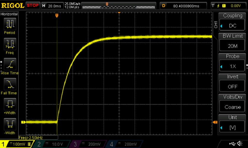
Figure 2-3 Rise time of current in magneto coil. Horizontal scale 20ms per box, vertical scale 0.2A per box
Let’s look at what happens when the magneto is spinning. Unlike the battery and coil powered engines, mag operated engines will have the igniter closed (shorted) and thus the magneto shorted except for a very short time when the igniter trips. Conservation of battery power is not an issue but the amount of time for the coil current to ramp up is. In Figure 2-1A, if one strand of wire is followed in the magneto coil it will be moving upward on one side of the housing in the magnetic field, it will then pass over the top and start downward through the magnetic field on the other side. With its output shorted, as it always is, this motion of the coil will result in the mag producing an AC (alternating) current as shown in Figure 2-4. Simply speaking, in the top half of Figure 2-4, electrons will be moving clockwise around the Figure 2-2 circuit, in the bottom half they will be moving counterclockwise (alternating back and forth).
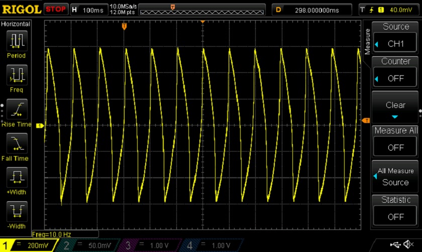
Figure 2-4 – Magneto short circuit output current. Vertical scale 0.4A /box, horizontal 100ms/box
While being turned at about 600 RPM the mag is producing first a positive direction peak current of about 1.2 amp. For the future any one of those peaks will be called Point A. The current then passes through zero to a peak of 1.2 amp in the negative direction (the negative peaks will be called Point B in the future). These 1.2A peaks will read about 0.72A on an analog AC multimeter. Analog AC meters don’t read peak value rather they read something which is generally rather close to the average. A home wall socket has about 170 V peaks which reads 120 V on an AC meter. The igniter will be timed to trip at one of those points that were called A or B, the peak current and peak stored energy point. Remember, the energy of the spark is the energy stored in the coil when the igniter trips. When the igniter trips the points very quickly open as if trying to instantly take the current to zero. But like the flywheel, the coil current cannot go to zero until all the stored energy is dissipated. The voltage rises across the igniter points causing the current to arc across and continue to flow until all the stored energy is dissipated. Again, the stored energy is converted to heat in the arc across the points.
There are some take away points here. First, as a simple analogy, in the mechanical world a spinning flywheel stores energy giving it momentum, in the electrical world a coil (inductor) stores energy and gives current momentum. You may have opened the igniter point but the current keeps flowing as if it has momentum. Second, the function of the magneto generator action is not to produce voltage rather it’s to produce as much current as possible in its coil. Third, the “hotness” of the spark as the igniter trips is dependent on the coils stored energy which rapidly increases with current. Therefore, the best measure of a good low-tension mag is its short circuit output current not its open circuit voltage as you may have heard and is as often stated (back to that later). To get a hot spark make sure the mag is in good mechanical condition, timed properly (trip at point A or B) and the magnet well charged, as a well charged magnet will produce maximum magnetic field and current.
A point of emphasis might be good here. The coil’s stored energy is the energy of the spark and that energy goes a current squared so it becomes critical that the igniter trips on one of those peak current point called A or B. The mag must be and stay in time, therefore it must turn at an exact multiple of the flywheel; 1X, 2X,3X…
As stated above one of the keys to good ignition is timing the mag properly. What if a mag is pulled off an engine and later it’s realized there are no timing marks? Not to worry! Short the output of the mag to its case while rotating the armature by hand. Every half turn it gets harder to turn, maybe even feeling as if its binding, these points are the maximum current outpoint points A and B in Figure 2-4. Either of those points are where the mag wants to be when the igniter trips. In the case of John Deere and many other mags, the max output occurs when the keyway in the armature shaft is straight up or down. If the valve timing and igniter timing are still intact, rotate the engine to exactly where the igniter trips. At the same time rotate the mag to the center of one of its binding points then turn the mag in its forward rotation direction 1 or 2 teeth, drop it in and bolt it down. You may not hit the timing perfectly but you will be close enough to run the engine nicely. Why was it rotated forward 1 or 2 teeth? Figure 2-2 shows that the current does not respond instantaneously in an inductor (coil) rather it slowly ramps to where it is going. The current which is the spark energy is delayed or lags the applied voltage (the generator action of the mag). Even though the peak output occurs at those two binding points when you turn the mag very slowly, at say 400RPM, the current is lagging. By moving the mag forward a couple of teeth gives the current a head start. Remember, the energy in the spark is the energy the coil has stored up and goes up as the current squared, so we need to be timed to fire at one of those peak currents.
It’s been said many times never pull the lead wire off a running magneto; its own voltage will destroy it. This might make some sense if the function of the mag was to generate the 100’s of volts necessary to cause an arc. But as has been discussed the function of the low-tension mag is to generate current and store energy in the coil. The magneto is never in a voltage generating mode but the output voltage can be looked at just for interest. Figure 2-5 shows the open circuit voltage (nothing connected to it) of the magneto in Figure 2-1B spinning about 600 RPM. Indeed, it gets rather high, peaking at 70V or thereabouts. The waveform is very distorted, however, and will read only about 10 volts on most analog meters. Because analog meters want to see a nice sinusoidal waveform, Figure 2-6, it is unlikely any two meters will read the same value. In fact, I read the distorted magneto voltage on 4 different meters with results of 8.5V (Radio Shack), 9V (unknown brand), 15V (BK digital) and 15V ($300 TruRMS). Nothing about the wave form seen in Figure 2-5 would suggest any of those numbers. Take a second to look again at the waveform an AC meter wants to see, Figure 2-6, and the waveform being fed to it, Figure 2-5. When disconnecting the magneto from the igniter more important than the magneto’s self-generated voltage is the fact that the magneto is directly connected to the igniter. When it trips, the coil current cannot stop immediately. If the coil current is going to continue to flow across the igniter gap a large voltage must develop on the igniter and thus the magneto. Figure 2-7 shows the voltage at the magneto terminal while attached to a 3HP John Deere engine running at about 550 RPM. Two interesting things can be seen here. First the coil being driven by the wimpy magneto has managed to create the 550 volts (p to p) necessary for the coil current to arc across the igniter gap. Second, in this John Deere case it takes about 75 microseconds (75uS, 0.000075S) for the stored energy to be dissipated. A couple of take away points; first don’t worry about disconnecting a spinning low-tension magneto, its self-induced voltage is well below the voltage it sees when the igniter trips (more about this later). Second, measuring the open circuit voltage of a spinning low-tension mag is not very useful as it’s never used in the voltage mode and so distorted that it’s not repeatable meter to meter.
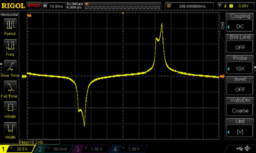
Figure 2-5 Open circuit voltage. Vertical scale 20V/box, horizontal 10ms/box
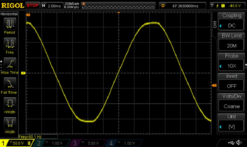
Figure 2-6 Wall socket sinusoidal wave form. Vertical scale 50V per box
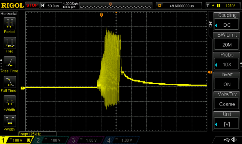
Figure 2-7 Voltage at Magneto when Igniter trips. Vertical scale 100V/box, horizontal 50uS/box
So, why have you been told to put a voltmeter on a low-tension mag and read its open circuit voltage while spinning it? It’s likely one of two reasons, either a lack of understanding or more likely, early meters and even low-cost meters today do not read AC current. The first meter capable of reading AC current was developed in the mid 1880’s. In the early 1900’s when rotary magneto companies were providing maintenance instructions, AC current meters were still only laboratory instruments. Reading AC current on a simple analog mechanical meter is difficult to do. If the available meter won’t read AC current, here are two recommended ways to measure the output of a low tension rotary mag that are better than measuring the output voltage. The first is relative and a bit subjective. Hook a 12V 5 Watt automotive lightbulb across the mag. At 500 to 600 RPM the light bulb should produce a bright flickering white light. If the light is weak and red in color the mag is weak. The second method is a more precise measurement, short the mag with a 2 ohm resistor and read the AC voltage across the resistor, Figure 2-8.
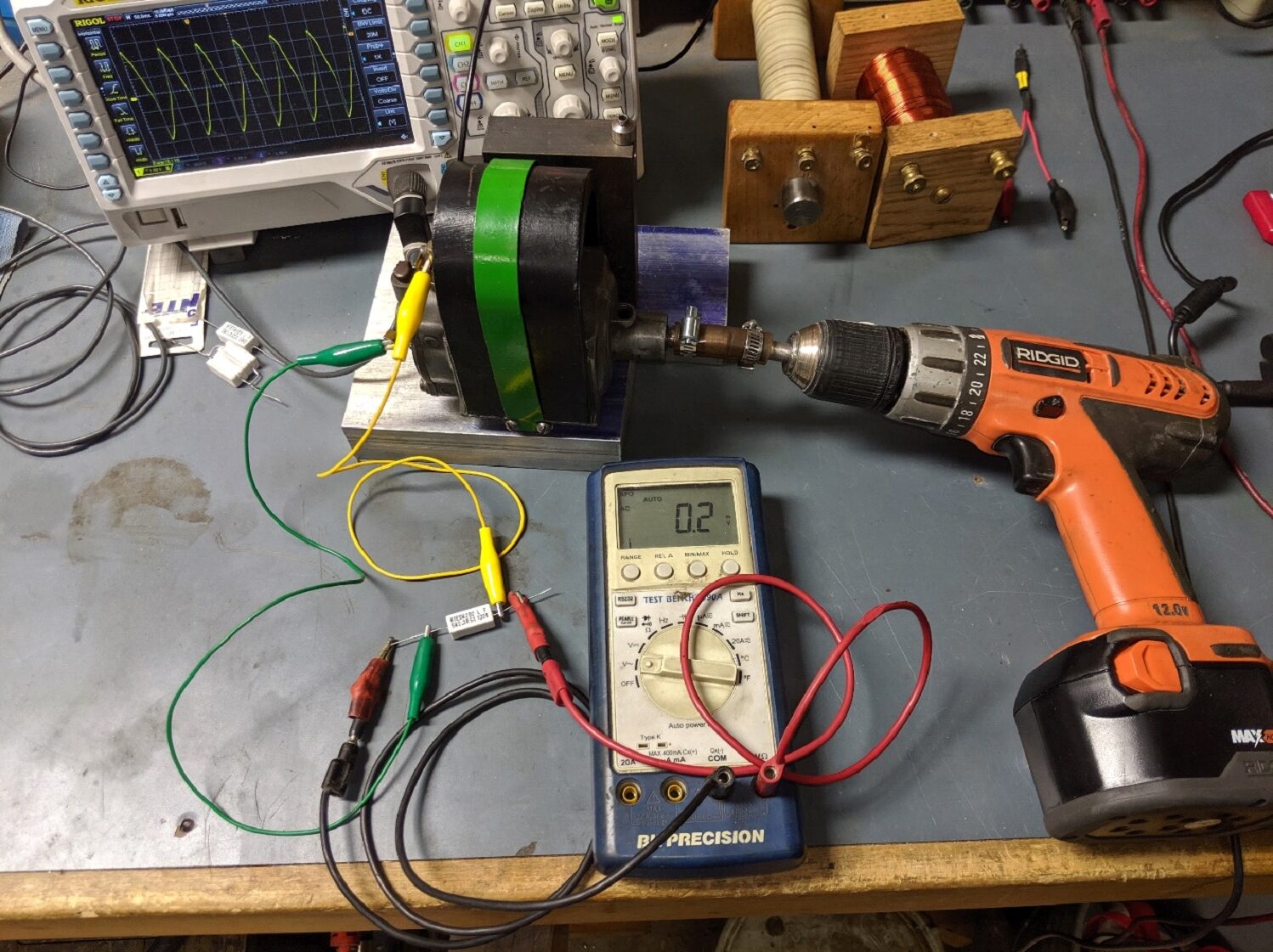
Figure 2-8 Measuring short circuit current
Here the yellow lead goes from the mag output tower to one side of the resistor, the green lead goes from the other side of the resistor to the body of the mag (ground), the volt meter is across the resistor. The mag is connected to the drill through a short piece of hose and spun 500 to 600 RPM. Although it’s not a real short circuit ( not as short as the closed igniter poins) it’s pretty good. Remember, the magneto coil has about 5 ohms of internal resistance, adding 2 ohms creates error but not a lot. You will now be reading the current through the resistor by reading the voltage drop the current causes as it passes through the resistor. Experience has shown that a mag that produces less than 0.7V across the 2 ohm resistor or less than 0.4A on an AC current meter or a red glow on a 12V 5 Watt bulb will not run an engine.
With the flywheel we know the heavier the load the faster it will stop spinning. In Figure 2-9 we see that it takes the magneto coil about 30ms to approach zero with a 15 ohm load, but arcing the igniter point it took only 75uS to approach zero as seen in Figure 2-7. Clearly the igniter points are a heavy load, dissipating the stored energy 400 times faster. If the magneto wire is pulled off a 3 horsepower John Deere running at about 550 RPM it takes about 25 seconds for the flywheels to dissipate their energy and coast to a stop. To stop them over 400 times quicker would require stopping them in less than 0.10 seconds. It is unlikely one could do that without shoving that crowbar that was used earlier into the spokes and seriously breaking something. That’s exactly what the coil does. It dumps its stored energy into the arc, breaking (ionizing) the gas in the arc path and heating it to an extremely high temperature. As a point of interest, electrons can not be seen. The spark seen is the result atoms being ionized by the electron stream. Ionization is the process of stripping electrons away from an atom. The visible spark seen is the process of those electrons reattaching.
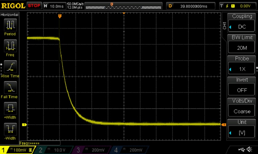
Figure 2-9 Magneto coil dissipating its energy through 15 ohms.
It is hoped that the preceding has given some insight of how low tension ignition systems work and why things like dwell time, current and coil energy are important.
David Cave
JDengines@cox.net