Final version Appeared In Gas Engine Magazine Aug/Sept 2020
I have long had an interest in old equipment used around our old engines. In pursuit of that interest, nearly 20 years ago, I found and bought sight unseen a Weidenhoff Model 818 magnet charger. Sitting on a bluff overlooking the Mississippi River, even unrestored, it was a beautiful sight to see. But why the fork lift? The advertisement made no mention of its weight. Back to Arizona we headed with the rear of our 4-wheel drive SUV sitting low. Loading it with a forklift was easy, unloading it with a cherry picker was another story. Getting the cherry picker boom in under the SUV roof line and above the Weidenhoff and chains to the corners of the pallet was a challenge. Once it was unloaded, I estimated its weight to be between 500 and 600 pounds by measuring how many pounds it took to pull the picker pump handle and multiplying that by piston diameters, arm lengths, etc.
Since then it has sat in my shop on a Harbor Freight dolly regularly recharging magnets. There have been a few cases where I have tested a low-tension magneto whose magnet had just been recharged on a home brew charger and one case after being recharged on a super charged John Rex style running on 24V. After a second recharge on the Weidenhoff the magneto output current of those magnets improved as much as 30% which translates to a 69% hotter spark. More recently, after I had originally written this article, I received a very weak welded John Deere magnet from Mitch Malcolm of Lightning Magneto. Knowing the condition of the magnet, Mitch felt I would be unable to revive it, and if I did it wouldn’t last more than a few days laying around without a keeper. The Weidenhoff brought it back to a very good level, not the best but never the less very good. I pulled the magnet off the magneto base and test stand and laid it on my wood workbench. The following week it was put back on the set up and tested again. Indeed, it lost 12% of its output but that still left it in the range of pretty good magnets I have tested. Five Mondays in a row I have put it back on the test stand, it has lost no strength since the first week. These examples would indicate that the Weidenhoff is a pretty good machine, but over the years I have been unable to find any documentation. After a search again this year for documentation with no results, I decided it was time to reverse engineer it and create my own documentation.
First, an external look. Figure 1 is a general view of the charger, with our 1945 Ford pickup in the background. Its physical dimensions are 27” x 20.5” x 14” (LWH). I now have an accurate digital scale that I can use to lift the charger under my gantry crane. Wow, 470 pounds. When the pole pieces, shown in Figure 1, are added in, the total weight is exactly 500 pounds. I felt pretty good that my very crude estimate was 500 to 600 pounds when the actual weight is 500. Continuing the external look, when turned on, the charger draws 15 Amps from the 120V line or 1800 Watts. For a home brew machine connected to a 12V car battery, the equivalent would be 150 Amps. The rear panel has the tag, Figure 2, with model and serial number 17264. The front panel, Figure 3, has two switches. The on/off switch is some form of arc suppression contactor. As the switch handle is smoothly moved and goes over center a set of springs slams the switch points open or closed with a noticeable bang. Why the contactor? Opening the switch here is identical to the igniter popping open on a battery and coil ignition. But rather than a small coil we have 2 giant coils and rather than a small spark we get a big arc. There was no snubber technology available at the time this machine was built so the switch takes a big hit every time it’s opened. The second switch selects 2 pole or 4 pole operation. There is large stiff wire attached to the on/off switch that forces the 2/4 pole switch to be in one position or the other. I’m not sure of a need for that other than to make the user think whether he needs to be in 2 pole or 4 pole mode. Figure 4, is a top view. The two main poles, the left one is North and the right one is South, the two smaller 4 pole operation poles are between them. The other end has storage, with a green velvet lining, for the pole pieces.

Figure 1 The Weidenhoff 818 with pole pieces.

Figure 2 Weidenhoff Model 818 tag.

Figure 3 Weidenhoff 818 front panel.

Figure 4 Weidenhoff 818 top view with John Deere magneto.
Now for a look internally. Figure 5, an overall view, has the electronics on the left and the big electromagnets on the right. In Figure 6, we have a better look at the magnet end. The bottom tie bar is huge, 14” x 8” x 3” thick, and has the two 4 pole pieces poured as an integral part.

Figure 5 Internal view of Weidenhoff 818.


Figure 6 Closer look at electromagnet coils and integral 4 pole shoe.
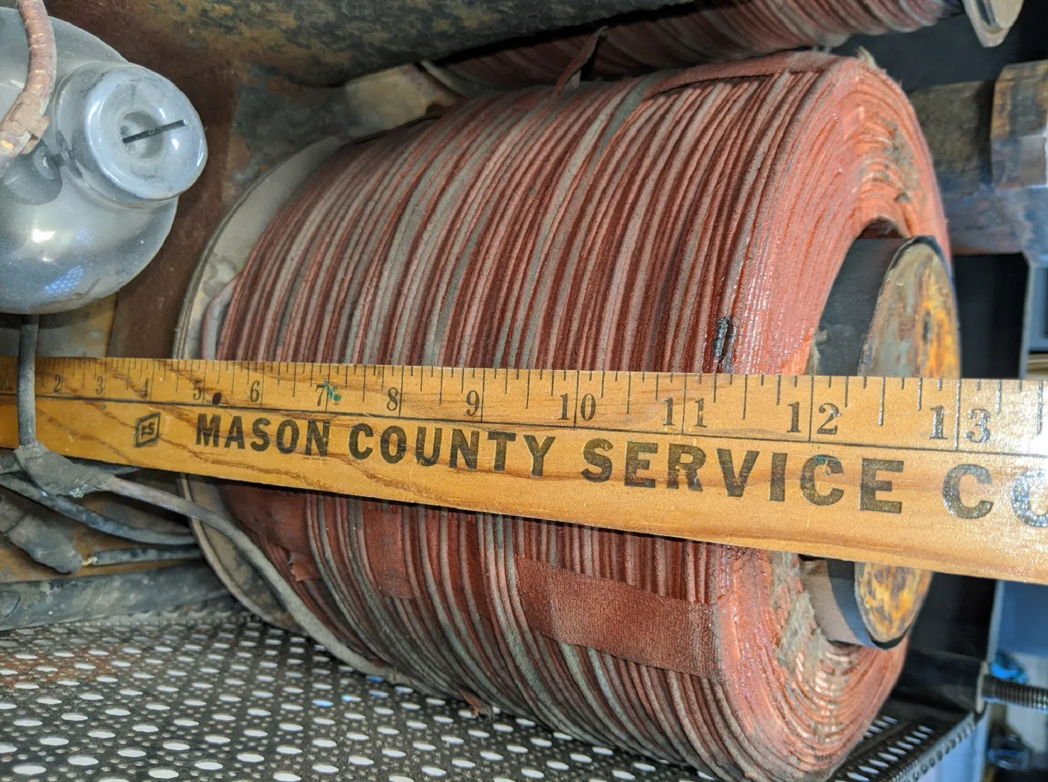
The core of each magnet coil is 10” tall with a 5” diameter, Figure 7 and 8. The wire bundle is 2 inches thick giving each coil the apparent diameter of 9”. The center to center separation is 10.5”. As best I can measure, on each coil, there are 21 layers of insulated 14-gauge wire with 77 turns end to end for a total of about 1600 turns. I estimate each coils wire length to be about 2500 feet. Each coil has 7.5Ω resistance and 700mH inductance. The chemistry of the big tie bar and the coil cores is unknown at this time.

Figure 7 Top view of N pole with pole piece removed.
Figure 8 Side view of N pole.
All of that was interesting but not very useful as it didn’t tell me the amp turns nor the magnetic field strength. For those, I needed the schematic. Figure 9 is, after several hours, what I believe to be the schematic. Very interesting! The 120V line comes into a large transformer with 16 taps. The output of the transformer feeds two complete and separate circuits for driving each coil individually. Each circuit uses two Tungar bulbs to rectify the transformed AC to a 120 pulses per second DC voltage. Tungar bulbs are Argon gas filled with a very hot filament (2.8V at 23A) cathode and a cold anode located above it. When the anode is positive with respect to the cathode electrons can leave (boiled off) the hot cathode and travel to the cold anode but when the cathode goes positive, they cannot leave the cold anode. The result is a pulsing one-way (DC) current. Figure 10 is a side view of a Tungar bulb and Figure 11 is an attempt to show the anode and cathode (filament). In operation the filament becomes very bright and the Argon gas glows, Figure 12. You may have noticed a 5th dark Tungar bulb in Figure 12, it’s a spare.

Figure 9 The Weidenhoff Model 818 schematic.

Figure 10 The Argon filled Tungar bulb.

Figure 11 The cold anode (looks like a hat) and heated cathode (looks like a tiny spring).
Figure 13 shows the pulsing DC voltage applied to each coil after passing thru the Tungar rectifiers, it’s about 120V peak. This is a distorted pulsing wave form and will likely read differently on all DC meters. On mine it reads about 65V average and a current of 9A average which is estimated to be about 16A peak. For those of you who like to turn your charger on and off while charging or like to bang the magnet with a hammer, the Weidenhoff does that 120 times a second. On average then the machine is about 28,800 Amp turns but 51,200 Amp turns at the peak of each 120-cycle pulse. At 0.070” separation the average magnetic field measures 1746mT, that would put the peak field at over 2T at the top of each pulse.

Figure 12 The Tungar bulbs under power.

Figure 13 Voltage applied to each coil.
For 4 pole operation the big S. pole coil is reversed by the 2/4 pole switch, becoming a second N pole. When connected in this manner the huge underlying tie bar becomes a S pole for both big coils causing both smaller shoes to become S poles at the top. In so doing, going around a circle at the surface in Figure 4, we see N, S, N, S.
Now that we have a schematic and understand how these big Weidenhoff machines operate, maintenance, trouble shooting and repairing in the future should be much easier. For example, replacing the Tungar bulbs with modern semiconductor diodes would be straight forward and eliminate the wasted power in the filaments and the voltage drop across the bulbs.
If any readers happen to have or come upon more information on the Model 818 or similar big 4 pole chargers, I would appreciate it if you would pass it along.
David Cave
JDengines@cox.net