A few years back a friend, Jim White, threw me a challenge. Could I make a simple all-electronic buzz coil? I had seen several schematics over the years but all of them required 2 or 3 power transistors, some form of oscillator and a car coil. The oscillators are usually the universal 555 timers which require several resistors and capacitors around them, while the standard car coil is big and heavy. After giving the challenge some thought, it seemed there ought to be a much simpler way.
The modern “1 coil per cylinder” method used in newer cars, as the name implies, puts a coil on each cylinder that is activated by a small 5V logic signal from the engine computer. Starting with one of those coils would have several advantages; power transistor built in, trigger mechanism built in and small size and light weight.
Using just 3 resistors, a GM LS2 engine coil and a capacitor, I created a pretty nasty buzz coil. By nasty I mean a much longer arc and a much faster spark rate than the old Model T type buzz coil. After building one for Jim and one for myself, I put the project on the shelf. In fact, never expecting to return to it I threw the schematic away. Recently however on an engine website the complex 555 timer system came up again. That inspired me to find out how Jim’s was doing. Turns out he has been using it for 4 years without a problem. Those things together with Evac 1 being so inexpensive and simple I thought it was time to get it back off the shelf and try to remember the resistor and capacitor values. One key point, is that it uses no pesky expensive semiconductors (transistors, integrated circuits, diodes, etc.) that can be put in backwards and blow up.
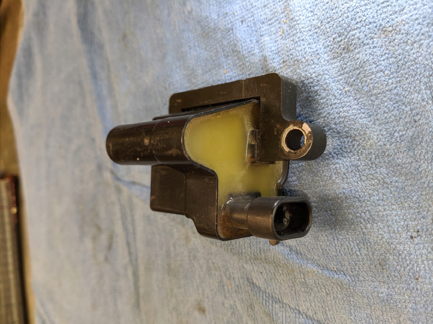
Figure 1 is a photo of one of the coils I picked up at a local junk yard. Four coils with the wire harness, which is one bank of a V8 engine, was very cheap ($20 at the time). You can also find new coils on the internet for $20 or less. An advantage of the junk yard route, even if you only need one, is the wire harness gives you the coil connector plugs (pigtail). For those who might be interested, Figure 2 is a simplified schematic of what’s inside a GM LS2 part number H6T55171ZC coil. At the junk yard it would be common on some 1999 to 2006 Chevy and GMC V8 engines. I found them on a 1999 Chevy Silverado Z71.

Figure 1. A used GM coil, part number H6T55171ZC
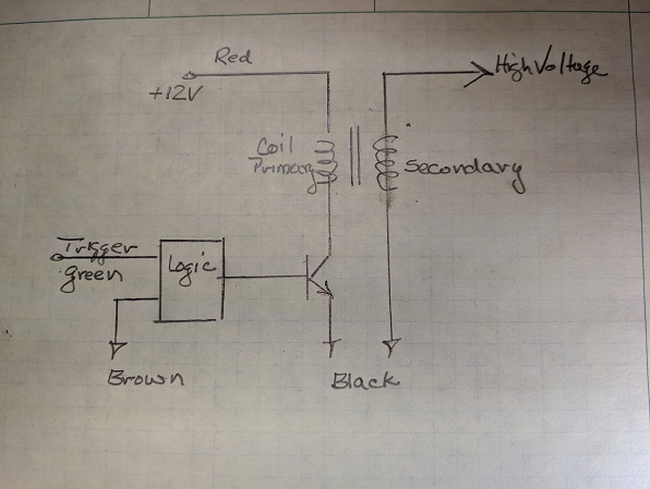
Figure 2. Inside the GM coil
Figure 3 is the very simple Evac 1 schematic. The two 15K Ω (ohm) resistors can’t be put in backwards nor can the 4.7µF capacitor if it’s a 50V version. If your capacitor is higher voltage, say 200V capability, its likely polarized and will need to go in oriented as shown. The 2.2 Ω resistor needs to be at least 5 watt but the two 15K Ω resistors can be any wattage.
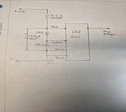
Figure 3. Evac 1 schematic
The components I used are shown in Figure 4. If your coil doesn’t have a connector plug you can cut some plastic back and get to the pins. If you orient the coil as I have, the pins left to right will be red, green, brown, black. The blue tube is a 14-16-gauge butt connector, it slides on to the coil’s high voltage pin very nicely.
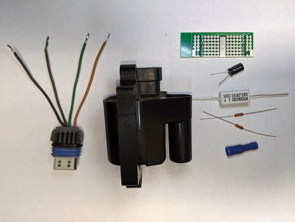
Figure 4. Evac 1 Components
Although the four components can be soldered and left hanging on the coil wires, I like to use a small prototype or vector board to make things more ridged and easier to secure in the box. Figure 5 is the assembly with the plug, ready to go in the box.
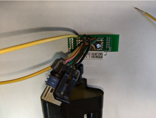
Figure 5. Evac 1 ready to go in the box
Figure 6 everything is in the box and ready to have the lid glued on. As a last step I have been squirting a bit of that infinitely expanding foam into the box. That last step keeps everything in place as it gets bounced around.
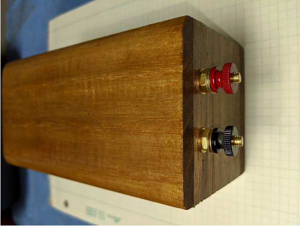
Figure 6. Evac 1
Once completed you will notice some differences between a Model T buzz coil and Evac 1. Generally, Evac 1 will throw a spark 2x longer than a buzz coil, sometimes up to 3/8 of an inch. Both take about 2mS from power on till the first spark. After the first spark, however, the buzz coil typically throws 500 sparks per second while Evac 1 throws 4000 per second. The buzz coil buzzes while Evac 1 howls. Also, a buzz coil generally doesn’t care which battery terminal is positive but Evac 1 does so I have colored the thumb nuts (red for positive).
The above information should give you a very nice buzz coil. I have found however that the capacitor is only need in very unusual operating conditions. Because there are conditions where it is needed, I have included it in the schematic but if you feel your operating conditions are near normal, leave it out. Most observable parameters stay about the same except time to first spark drops to 0.5mS, way faster than a Model T buzz coil. When the capacitor is left out, Evac 1 becomes even simpler; 3 resistors and a coil. Also, almost any LS 2,3 or 4 engine coil will likely work. Figure 7 is a capacitorless unit built on a LS3 coil, part number 12573190. For this build I used a Dremel tool to cut the hood and expose the pins. The 3 resistors and the ground wire were directly soldered to the coil pins. It would be a good idea to use shrink tubing or spaghetti on the exposed leads.
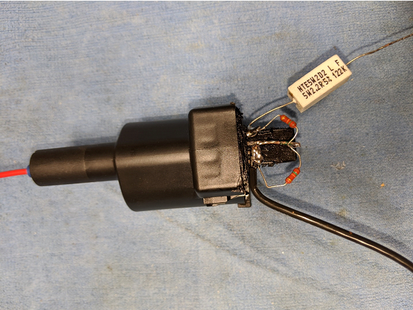
Figure 7. Components soldered directly to LS3 coil pins
The Evac 1 schematic shown is for intermittent use only, for example gas engines. If used continuously for say one minute continuous “on” time or more than 30% duty cycle, the 2.2 Ω resistor power rating should be raised to 15Watts.
The 4000, or so, sparks per second allow very little dwell time for the coil thus limiting the output voltage and arc length to around 3/8 inch. If you desire a show and tell only coil, increase the capacitor to 6800µF (or some large value). The rep rate will drop to 50 per second but arc length can exceed 3/4”. It will however not be useful on an engine as the delay to first spark becomes large, thus retarding the engine spark to the point the engine won’t run.
Sometimes connection to a sparkplug engine can be confusing. Figure 8 is the connection used by John Deere on their sparkplug engines (12V rather than 6V, Evac 1 rather than buzz coil).
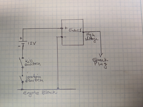
Figure 8. Connection of Evac 1 to gas engine
That, as I said, is the John Deere recommendation. The order of the battery, kill switch and the engine ignition switch are however arbitrary, you may interchange their location at will.
David Cave Ph.D.
JDengines@cox.net